
Wind-Solar Hybrid Power Model

Wind power generation and solar power generation are combined to make a WIND-SOLAR HYBRID POWER GENERATION SYSTEM. A 6v, 5Ah lead-acid battery is used to store solar power and charging is controlled by a charger circuit.

Design Estimation of 5KWp BIPV Solar Power System

Design Estimation of 5KWp BIPV Solar Power System

Intenet access through LED Bulb

A new emerging technology for internet and data sharing. data can be sent and recieved at speed of 100gbps.

Hydrogen Fuel Cell !!! New source of 'R'energy

This is the world’s first scalable Hydrogen-On-Demand process requiring minimum power input

Download Free Android App For REnergy!!

This is a free android app for this blog : REnergy. I've built this app for the users of my blog to access my posts, works with ease.

Friday, 3 May 2013

Internet Access Through LED bulb: Li-Fi

Imagine you are standing under a street light to get public internet access, or downloading a HD full movie from the lamp of your desk in  a few seconds, or posting your just clicked snap during a flight. No, I'm not talking about an upcoming Sci-Fi movie. There  is a newborn technology, which could meet the ever-increasing demand for high-speed wireless connectivity. Radio waves are replaced by light waves in a new method of data transmission which is being called Li-Fi.


Genesis

The technology Li-Fi was pioneered by German physicist Harald Haas, currently based at the University of Edinburgh in the UK. Haas coined the term Li-Fi in 2011 in the context of a talk presenting the new technology at the TED (Technology Entertainment and Design) Global conference. The word quickly entered common parlance as an instantly recognizable alternative to WiFi. Both terms are examples of abbreviations linguists sometimes describe as clipped forms, i.e. WiFi = wireless fidelity, Li-Fi = light fidelity. Haas's research project, originally known as D-Light (short for Data Light), is now set to launch a prototype Li-Fi application under the name of newly-formed company VLC (Visible Light Communication) Ltd, which was set up to commercialize the technology. 
Prof. Harald Haas, Edinburgh, Germany


According to researchers led by a team from the University of Strathclyde, it could be possible to combine domestic lighting to also illuminate homes with the technology, which claims to offer high-definition film downloads in under a minute. Professor Martin Dawson, of Strathclyde, who is leading the four-year initiative, said “Imagine an LED array beside a motorway helping to light the road, displaying the latest traffic updates and transmitting internet information wirelessly to passengers’ laptops, netbooks and smartphones. This is the kind of extraordinary, energy-saving parallelism that we believe our pioneering technology could deliver.”


How Li-Fi Works?

Li-Fi is typically implemented using white LED light bulbs at the downlink transmitter. These devices are normally used for illumination only by applying a constant current. However, by fast and subtle variations of the current, the optical output can be made to vary at extremely high speeds. This very property of optical current is used in Li-Fi setup. The operational procedure is very simple-, if the LED is on, you transmit a
digital 1, if it’s off you transmit a 0. The LEDs can be switched on and off very quickly, which gives nice opportunities for transmitting data. Hence all that is required is some LEDs and a controller that code data into those LEDs. All one has to do is to vary the rate at which the LED’s flicker depending upon the data we want to encode. Further enhancements can be made in this method, like using an array of LEDs for parallel data transmission, or using mixtures of red, green and blue LEDs to alter the light’s frequency with each frequency encoding a different data channel. Such advancements promise a theoretical speed of 10 Gbps – meaning one can download a full high-definition film in just 30 seconds.
 A novel modulation technique coined SIM-OFDM was recently proposed. SIM-OFDM uses different frequency carrier states to convey information and leads to increased performance in comparison to conventional OFDM. Additionally, its innovative structure can lead to a decrease of the peak system power, which is highly beneficial in the context of optical wireless communication.

Economic value

  • A free band that does not need license.
  • High installment cost but very low maintenance cost.
  • Cheaper than Wi-Fi.
  • Theoretical speed up to 1 GB per second : Less time & energy consumption.
  • No more monthly broadband bills.
  • Lower electricity costs.
  • Longevity of LED bulb : saves money.
  • Light doesn't penetrate through walls : secured access.

Limitations

The main problem is that light can't pass through objects, so if the receiver is inadvertently blocked in any way, then the signal will immediately cut out. "If the light signal is blocked, or when you need to use your device to send information -- you can seamlessly switch back over to radio waves", Harald says.
Reliability and network coverage are the major issues to be considered by the companies while providing VLC services. Interferences from external light sources like sun light, normal bulbs; and opaque materials in the path of transmission will cause interruption in the communication. High installation cost of the VLC systems can be complemented by large-scale implementation of VLC though Adopting VLC technology will reduce further operating costs like electricity charges, maintenance charges etc.

Future Prospects

This research report categorizes the global VLC technology market; based on component, applications, and geography. Li-Fi uses light-emitting diodes (LEDs) which are rapidly gaining in popularity for standard lightbulbs and other domestic and commercial purposes. They are expected to be ubiquitous in 20 years. VLC is not in competition with WiFi, Prof. Haas says, it is a complimentary technology that should eventually help free up much needed space within the radio wave spectrum.
"We still need Wi-Fi, we still need radio frequency cellular systems. You can't have a light bulb that provides data to a high-speed moving object or to provide data in a remote area where there are trees and walls and obstacles behind," he says.

some hotspots are:

  • the remote control devices under the ocean : radio wave doesn't work there.
  • petrochemical plants : radio wave data tranmission is not secured there.
  • hospitals : for medical purpose.
  • street lights, traffic signals : for traffic update.
    • aircraft cabins : for emmegency conversations.


    A power point slideshow on this topic provided here.Please give your valuable feedback.


      Thursday, 2 May 2013

      Lead-Acid Battery charger circuit

      In this article i'm going to discuss about a lead-acid battery chrager construction and a very basic principle of charging ckt. Also i'll share my own battery charger that i've built to use my project.


      Brief Description
      Input of this prototype is 12v,1amp DC power supply.using a voltage regulator IC, a comparator IC and a Double transistor package module the circuit gives output of 6v DC.  A 6v, 5Ah lead-acid battery can be charged using this circuit.

      Circuit Design:


      LM 317


      Components Used:
      ICs:
      a) LM 317 (v-reg) - 1
      b) IC 741 (comparator) - 1
      c) TIP 122 (transistors) - 1
      Resistors:(all are 1/4 watts)
      470 ohms: 1
      220 ohms: 1
      100 ohms: 1
      10k ohms: 1
      1k   ohms: 1
      100kohms:1
      2k2 preset pot:1
      10k preset pot:1
      Diodes:
      1N4007 : 2
      3.3v Zener : 2
      0.1uF capacitor : 1(disk type)
      LED: green & red : one each


      IC 741


      Testing of the Circuit
      1)    The input to the circuit can be fed from a standard 12V 1 amp adapter.

      2)    To set up the circuit initially do not connect any battery.

      3)    Feed 12V input, adjust the 2K2 pot to get 7v across the battery charging terminals.

      4)    Next, adjust the 10K preset such that the green LED just lights up fully and the red LED shuts off.

      5)    Circuit has been set.

      6)    Switch OFF power. Connect a discharged battery and switch ON power, the circuit will do the rest.it will cut off as as soon as the battery voltage reaches 7V.


      The prototype model i've built:

       1. this is the circuit set-up in 3.5x6 inches box. Input of this circuit comes from two 6v, 3watt solar modules connected in series to get 12v,1amp DC output.

      2. the output of the circuit is connected to a 6v,5Ah lead-acid battery which is fully charged.
      that' why the RED LED is lighted up.
      3. you can see the multi-meter reading.
      It shows that the battery-voltage is 6.36v. and because of that the RED LED is blinking.

      What does 64K means In a SIM Card?

      Many of us don’t know the meaning of 64k written on the SIM card. In many forum it is said the the 64K is refer to the total memory available in the SIM card. I don’t know whether it is correct or not. Recently I was studying the digital communication subject. In this subject there is a chapter of Pulse Code Modulation (PCM) and Digital Multiplexers. In this chapter, I found a topic on TI carrier system(PCM-TDM System). It says that according to North-American hierarchy of telephony system-both for analog and digital system- a PCM voice signal represents 64k bits/sec i.e., 8000 samples per sec x 8 bits per sec.. also that due to 8000 samples per sec, the sampling rate, the time duration between adjacent samples will be (1/8000) or 125 micro seconds.
      Now you can see that in actual telephony system, 64K stands for the data transfer rate and of course the speed of data (digital signal) transfer. higher the rate, higher speed of data accessing and transferring. Some years back, when the mobile phones came into market, you might have noticed that 32K was written on the place of 64K of now-a-days SIM card. that means the data transfer rate was very low then and we could not surf/browse internet thru’ our mobile phones. Today, 64K, 128K SIM Cards are available. We all know that 64K is 2G and 128K SIMs are 3G.
      So , according to my limited knowledge, 64K should stands for the data transfer rate or to be more precious, the sampling rate of that particular SIM card. I’m posting details of T1 carrier system here. To know more please go thru’ the next part.
      T1-carrier System
      The T-carrier system, introduced by the Bell System in the U.S. in the 1960s, was the first successful system that supported digitized voice transmission. The original transmission rate (1.544 Mbps) in the T1 line is in common use today in Internet service provider (ISP) connections to the Internet. Another level, the T3 line, providing 44.736 Mbps, is also commonly used by Internet service providers.

      The T-carrier system is entirely digital, using pulse code modulation (PCM) and time-division multiplexing (TDM). The system uses four wires and provides duplex capability (two wires for receiving and two for sending at the same time). The T1 digital stream consists of 24 64-Kbps channels that are multiplexed. (The standardized 64 Kbps channel is based on the bandwidth required for a voice conversation.) The four wires were originally a pair of twisted pair copper wires, but can now also include coaxial cable, optical fiber, digital microwave, and other media. A number of variations on the number and use of channels are possible.
      A T1 line in which each channel serves a different application is known as integrated T1 or channelized T1. Another commonly installed service is a fractional T1, which is the rental of some portion of the 24 channels in a T1 line, with the other channels going unused.

      In the T1 system, voice or other analog signals are sampled 8,000 times a second and each sample is digitized into an 8-bit word. With 24 channels being digitized at the same time, a 192-bit frame (24 channels each with an 8-bit word) is thus being transmitted 8,000 times a second. Each frame is separated from the next by a single bit, making a 193-bit block. The 192 bit frame multiplied by 8,000 and the additional 8,000 framing bits make up the T1's 1.544 Mbps data rate. The signaling bits are the least significant bits in each frame.


      CABLE TESTER

      Have you ever wondered if a particular cable is delivering mains power supply to your device or not? Here is a solution that helps you test cable continuity without requiring any physical contact with the bare cable. The circuit practically detects AC signal frequencies and gives an LED indication if the cable is conducting. The circuit is highly sensitive and can detect signals from the surface of the cable itself and thus no direct contact with the bare cable is necessary.
      The circuit can be used to test other cables, including modem, audio/video and dish antenna cables to name a few.


      Circuit and working 
      Above figure shows the circuit of cable tester. The circuit is built around op-amp CA3130 (IC1). IC1 is a BiMOS operational amplifier with MOSFET inputs and CMOS output. It has P-MOS transistors in the inputs for providing very high input impedance and very good speed performance. The input readily accepts even weak signals.

      IC1 is wired as a non-inverting amplifier with feedback resistors R6 and R7 to set the closed-loop voltage gain. Capacitor C1 is added to provide a progressive roll-off. The non-inverting input of IC1 is biased by a combination of resistors R1 through R5. Capacitor C2 is added between the offset null (pin 1) and Strobe (pin 8) pins for phase compensation.

      Working of the circuit is simple. Bring antenna of the circuit near the cable that you want to test. The LED will glow if the cable is conducting perfectly.


                                                                 Component layout for the PCB
                                                                  Actual-size, single-side PCB for cable tester
      Construction and testing
      An actual-size, single-side PCB for the cable tester is shown in Fig. 2 and its component layout in Fig. 3. After assembling the circuit on the PCB, enclose it in a suitable case. Antenna can be a telescopic antenna or a 10cm long wire.

      To test the circuit, check 9V at test point TP1 with respect to TP0 to verify the correct power supply to the circuit. Bring antenna of the assembled circuit near some power cable and check status of LED1.


      Wednesday, 1 May 2013

      Features of a Solar Inverter

      When it comes to setting up a solar inverter (for any type), the engineer/installer have to ask for certain features or you can say the qualities to the manufacturer because lacking of these feature in a inverter causing the system in-efficient. So in this post, i'll discuss about those particular features that we are looking for at the time of purchasing/installing solar inverter.


      1.    Maximum Power Point Tracking

      Solar inverters use maximum power point tracking (MPPT) to get the maximum possible power from the PV array. Solar cells have a complex relationship between solar irradiation, temperature and total resistance that produces a non-linear output efficiency known as the I-V curve. It is the purpose of the MPPT system to sample the output of the cells and determine a resistance (load) to obtain maximum power f or any given environmental conditions. Essentially, this defines the current that the inverter should draw from the PV in order to get the maximum possible power (since power equals voltage times current).


      In this image you can see that if we use a inverter which works without an MPPT algorithm, then the system become in-efficient or in other words there will be losses in utilizing the solar power. But we use an inverter which works on a MPPT algorithm thenthe utilizing of power is far better.


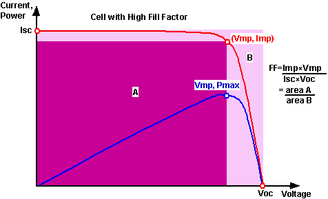
      Now, we should know about the Fill-Factor. what is Fill Factor or FF
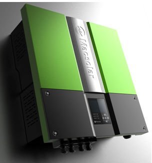
      The fill f actor, more commonly known by its abbreviation FF, is a parameter which, in conjunction with the open circuit voltage and short circuit current of the panel, determines the maximum power from a solar cell. A solar micro-inverter in the process of being installed . The ground wire is attached to the lug and the panel's DC connections are attached to the cables on the lower right. The AC parallel trunk open circuit voltage and short circuit current of the panel, determines the maximum power from a solar cell. Fill f actor is def ined as the ratio of the maximum power f rom the solar cell to the product of Voc and Isc.
       There are three main types of MPPT algorithms: perturb-and-observe, incremental conductance and constant voltage. The first two methods are often referred to as hill climbing methods; they rely on the curve of power plotted against voltage rising to the left of the maximum power point, and falling on the right.

      MPPT With FF Display

      A general algorithm of MPPT shown here.


      2.   Anti-Islanding Protection

      In the event of a power failure on the grid, it is generally required that any grid-tie inverters attached to the grid turn off in a short period of time. This prevents the inverters from continuing to feed power into small sections of the grid, known as "islands". Powered islands present a risk to workers who may expect the area to be unpowered, but equally important is the issue that without a grid signal to synchronize to, the power output of the inverters may drift from the tolerances required by customer equipment connected within the island. 

      Detecting the presence or lack of a grid source would appear to be simple, and in the case of a single inverter in any given possible physical island (between disconnects on the distribution lines f or instance) the chance that an inverter would f ail to notice the loss of the grid is effectively zero. However, if there are two inverters in a given island, things become considerably more complex. It is possible that the signal from one can be interpreted  as a grid feed from the other, and vice versa, so both units continue operation. As they track each other's output, the two can drift away from the limits imposed by the grid connections, say in voltage or frequency.

       There are a wide variety of methodologies used to detect an islanding condition. None of these are considered fool-proof , and utility companies continue to impose limits on the number and total power of solar power systems connected in any given area. However, many in-field tests have failed to uncover any real-world islanding issues, and the issue remains contentious within the industry.


      3.    Redundancy

      Redundancy is one of the main reason string inverters and microinverters are chosen instead of central inverters because in case of failure a smaller part of the system will be affected. String inverters have the added benefit of being a standard readily available commercial component which means it’s possible to let a local installer or facility manager exchange the inverter if necessary; also extra inverters can be kept in stock for quick exchange. Conversely, service contracts should be offered with central inverters and they should be serviced only by trained experts.

      4.  Total Harmonic Distortion

      The total harmonic distortion, or THD, of a signal is a measurement of the harmonic distortion present and is defined as the ratio of the sum of the powers of all harmonic components to the power of the fundamental frequency. THD is used to characterize the linearity of audio systems and the power quality of electric power systems.
      So, it is desired that a inverter should have feature to cancel out the most of the higher harmonics as possible

      .


      When the input is a pure sine wave, the measurement is most commonly the ratio of the sum of the powers of all higher harmonic frequencies to the power at the first harmonic, or fundamental, frequency.
       \mbox{THD} = \frac{P_2 + P_3 + P_4 + \cdots + P_\infty}{P_1} = \frac{\displaystyle\sum_{i=2}^\infty P_i}{P_1}
      which can equivalently be written as
       \mbox{THD} =  \frac{P_\mathrm{total} - P_1}{P_1}
      if there is no source of power other than the signal and its harmonics.
      Measurements based on amplitudes (e.g. voltage or current) must be converted to powers to make addition of harmonics distortion meaningful. For a voltage signal, for example, the ratio of the squares of the RMS voltages is equivalent to the power ratio:
       \mbox{THD} =  \frac{V_2^2 + V_3^2 + V_4^2 + \cdots + V_\infty^2}{V_1^2}
      where Vi is the RMS voltage of ith harmonic and i = 1 is the fundamental frequency.
      THD is also commonly defined as an amplitude ratio rather than a power ratio,[3] resulting in a definition of THD which is the square root of that given above:
       \mbox{THD} = \frac{ \sqrt{V_2^2 + V_3^2 + V_4^2 + \cdots + V_\infty^2} }{V_1}
      This latter definition is commonly used in audio distortion (percentage THD) specifications. It is unfortunate that these two conflicting definitions of THD (one as a power ratio and the other as an amplitude ratio) are both in common usage.
      So, it is desired that a inverter should have feature to cancel out the most of the higher harmonics as possible.


      Follow me on Academia.edu
      About the Author

      Amrit Mandal is a final year B.tech (EE) Student, Admin of this blog. He likes to work in the renewable energy field-specially in solar energy field.
      Follow Us on Twitter #REnergy_Blog

      REnergy

      Tuesday, 30 April 2013

      Solar Inverter : Classification

      The solar inverter is a critical component in a solar energy system. It performs the conversion of the variable DC output of the Photovoltaic (PV) module(s) into a clean sinusoidal 50- or 60 Hz AC current that is then applied directly to the commercial electrical grid or to a local, off-grid electrical network. Typically, communications capability is included so users can monitor the inverter and report on power and operating conditions, provide firmware updates and control the inverter grid connection. Depending on the grid infrastructure wired (RS-485, CAN, Power Line Communication, Ethernet) or wireless (Bluetooth, ZigBee/IEEE802.15.4, 6loWPAN) networking options can be used. To know more about solar inverter please view the post.


      Function Of a Solar Inverter


      A solar inverter, or PV inverter, converts the
      variable direct current (DC) output of a photovoltaic
      (PV) solar panel into a utility frequency alternating
      current (AC) that can be fed into a commercial
      electrical grid or used by a local, off-grid electrical
      network. It is a critical component in a photovoltaic
      system, allowing the use of ordinary commercial
      appliances. Solar inverters have special f unctions
      adapted f or use with photovoltaic arrays, including
      maximum power point tracking and anti-islanding
      protection.


      A little More About Solar Inverters

      The engineering of these solar inverters and solar panels are designed like pieces of puzzles which should fit together in order to function. Conclusively, these solar inverters are programmed to hook up to a specific count of solar boards. The cost of inverter is practically 10 percent of the total cost of the solar board. We have to take note that these solar inverters do not have useful lives equally long as that of solar panels. This means you have to replace your solar inverters from time to time for you to use your solar system for its remaining useful life. For a solar inverter to work efficiently it should have adequate solar panels connected to it. Lesser or more panels that are connected to it could cause it not to function properly. Consequently, it should have at least 95 percent of panels hooked up to obtain optimum performance.


      Classification

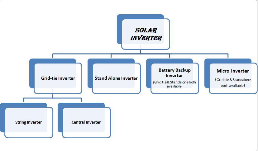
      Solar Inverter can be classified into 4 major type.They are:

      1. Stand-alone inverters 

      used in isolated systems where the inverter draws its DC energy f rom batteries charged by photovoltaic arrays. Many stand-alone inverters also incorporate integral battery chargers to replenish the battery f rom an AC source, when available. Normally these do not interf ace in any way with the utility grid, and as such, are not required to have anti-islanding protection.


        2.  Grid-Tie Inverters

      This type of inverters match phase with a utilitysupplied sine wave. Grid-tie inverters are designed to shut down automatically upon loss of utility supply, f or safety reasons. They do not provide backup power during utility outages.


      3.   Battery Backup Inverters

      Thsese are special inverters which are designed to draw energy from a battery, manage the battery charge via an onboard charger, and export excess energy to the utility grid. These inverters are capable of supplying AC energy to selected loads during a utility outage, and are required to have anti-islanding protection.


      4.   Micro-Solar Inverter

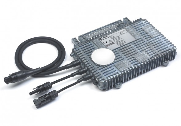
      Solar micro-inverters convert direct current (DC) from a single solar panel to alternating current (AC). The electric power f rom several micro-inverters is combined and sent to the consuming devices. The key feature of a micro-inverter is not its small size or power rating, but its one-to-one control over a single panel and its mounting on the panel or near it which allows it to isolate and tune the output of that panel.
      these micro inverters are most suitable for domestic-solar PV-application where the no. of solar panels are limited to few. Detail about the Micro-solar inverter will be cited in another post.


      Here is Heirarchy Model of Solar Inverter Classification


      Follow me on Academia.edu
      About the Author

      Amrit Mandal is a final year B.tech (EE) Student, Admin of this blog. He likes to work in the renewable energy field-specially in solar energy field.
      Follow Us on Twitter #REnergy_Blog

      REnergy

      Monday, 29 April 2013

      LITER OF LIGHT


      We dream about tomorrow’s glowing world………...........We are the team of “Liter of Light” in India……..
      Mission
      spreading this innovation in our country and installing the liter of light in India.
      Description
      The  source of light consists of a plastic bottle filled with a water solution which is embedded in the roofs of houses. The solar bottle harnesses the light from the sun, capturing and diffracting the light to all parts of the room. Our aim is to support this idea which has already launched in many countries around the world.
       Founded - September 12,2011
      Products- A soda bottle as a light source in underprivileged households.


      Liter of Light India Abstract :
                   We are a group of under graduate students working to install liter of lights or solar blubs all over India.Our motto is to lighten up the most unprivileged communities by installing solar bulbs.Introducing such low-cost technologies we aim to glow about one million homes throughout India.
      What is Liter of Light :
                    A Liter of Light is a zero-carbon emitting solar lighting project which is first initiated by members of My Shelter Foundation and students of the Massachusetts Institute of Technology.Solar Bottle Bulb uses appropriate technologies that are highly replicable and sustainable. The materials used are found easily in the poorest neighborhood.They can be easily built with simple carpentry skills and little knowledge about the solar bulb. This simple mechanism of installing Solar Bottle Bulb made the expansion of movement easy.
      Do it Yourself Liter of Light:
                     The bulb is nothing but a A 1.5 liter clear PET bottle which is used as source of light.It is filled with the mixture of water and bleach.The bottle with this mixture is inserted into a metal sheet.This kit is embedded on the roofs of houses which acts as a source of light.
      Working principle of Liter of Light :
                      Solar Bottle Bulb works by the refraction of light rays.The sun rays falling on the bottle gets refracted when it immediately enters water i.e. due to change in medium form air to water.This refracted light spreads at an angle of 360 degrees in a room and produces light equivalent to 60 watts bulb.
                      The solar bulb lasts for 5 years without any sort of maintenance with the change of water at regular intervals.Bleach is added to maintain the clarity of water and make the water free from microorganisms.
       Why Liter of Light :

      • Solar Bottle Bulb does not have any carbon emissions when compared to any conventional light.
      • Solar Bottle Bulb is a source of livelihood for the local unemployed people.
      • It is very economic and reliable.
      • It reduces the impact of global warming on earth.
      • Disposed plastic is up-cycled.
          https://www.facebook.com/pages/Liter-of-Light-in-India/204926342960861 - FOLLOW THIS LINK .