


It is the purpose of the MPPT system to sample the output of the cells and determine a resistance (load) to obtain maximum power f or any given environmental conditions. Essentially, this defines the current that the inverter should draw from the PV in order to get the maximum possible power (since power equals voltage times current).
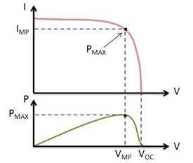 |
| The current and voltage at which a solar module generates the maximum power is known as the maximum power point |
Different Types of MPPT Algorithm
There are various methods or algorithms available to implement Maximum Power Point Tracking. Among them, the most efficient and commonly used methods are-
- Perturb & Observe Method (P&O)
- Incremental Conductance Method (INC)
- Constant Voltage Method
- Current Sweep Method
- Perturb & Observe Method (P&O)
In this method, the device (controller/inverter) adjusts the voltage by a small amount from the array and measures power; if the power increases, further adjustments in that direction are tried until power no longer increases. This method is most common, although this method can result in oscillations of power output. It is referred to as a hill climbing method, because it depends on the rise of the curve of power against voltage below the maximum power point, and the fall above that point. Perturb and observe is the most commonly used MPPT method due to its ease of implementation. This method may result in top-level efficiency, provided that a proper predictive and adaptive hill climbing strategy is adopted.
I've added a flowchart for better understanding of this Method.

- Incremental Conductance Method
In the incremental conductance method, the controller measures incremental changes in array current and voltage to predict the effect of a voltage change. This method requires more computation in the controller, but can track changing conditions more rapidly than the perturb and observe method (P&O). Like the P&O algorithm, it can produce oscillations in power output. This method utilizes the incremental conductance (dI/dV) of the photovoltaic array to compute the sign of the change in power with respect to voltage (dP/dV).
The incremental conductance method computes the maximum power point by comparison of the incremental conductance (ΔI/ΔV) to the array conductance (I/V). When these two are the same (I/V=ΔI/ΔV), the output voltage is the MPP voltage. The controller maintains this voltage until the irradiation changes and the process is repeated.


For Further details on Perturb and Observe Method, please follow this link: Perturb and Observe Method
Follow me on Academia.edu


 Many of us don’t know the meaning of 64k written on the SIM card. In many forum it is said the the 64K is refer to the total memory available in the SIM card. I don’t know whether it is correct or not. Recently I was studying the digital communication subject. In this subject there is a chapter of Pulse Code Modulation (PCM) and Digital Multiplexers. In this chapter, I found a topic on TI carrier system(PCM-TDM System). It says that according to North-American hierarchy of telephony system-both for analog and digital system- a PCM voice signal represents 64k bits/sec i.e., 8000 samples per sec x 8 bits per sec.. also that due to 8000 samples per sec, the sampling rate, the time duration between adjacent samples will be (1/8000) or 125 micro seconds.


