
Wind-Solar Hybrid Power Model

Wind power generation and solar power generation are combined to make a WIND-SOLAR HYBRID POWER GENERATION SYSTEM. A 6v, 5Ah lead-acid battery is used to store solar power and charging is controlled by a charger circuit.

Design Estimation of 5KWp BIPV Solar Power System

Design Estimation of 5KWp BIPV Solar Power System

Intenet access through LED Bulb

A new emerging technology for internet and data sharing. data can be sent and recieved at speed of 100gbps.

Hydrogen Fuel Cell !!! New source of 'R'energy

This is the world’s first scalable Hydrogen-On-Demand process requiring minimum power input

Download Free Android App For REnergy!!

This is a free android app for this blog : REnergy. I've built this app for the users of my blog to access my posts, works with ease.

Showing posts with label projects. Show all posts

Friday, 10 May 2013

Commonly Used Algorithms for MPPT

The amount of electrical power generated by a photovoltaic system depends on solar irradiance (solar energy per unit area of the solar panel’s surface) and other conditions such as temperature and cloud cover. The current and voltage at which a solar module generates the maximum power is known as the maximum power point. The location of the maximum power point is not known in advance.Solar inverters or charge controllers use maximum power point tracking (MPPT) to get the maximum possible power from the PV array. Solar cells have a complex relationship between solar irradiation, temperature and total resistance that produces a non-linear output efficiency known as the I-V curve.
It is the purpose of the MPPT system to sample the output of the cells and determine a resistance (load) to obtain maximum power f or any given environmental conditions. Essentially, this defines the current that the inverter should draw from the PV in order to get the maximum possible power (since power equals voltage times current).
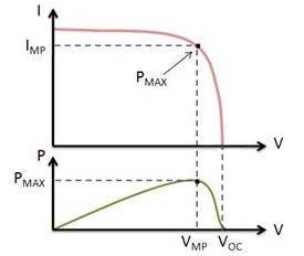
The current and voltage at which a solar module generates the maximum power is known as the maximum power point
Maximum power point tracking (MPPT) modifies the electrical operating point of a solar energy system to ensure it generates the maximum amount of power. This involves finding the current or voltage of the solar panel at which maximum power can be generated. MPPT improves the electrical efficiency of a solar energy system, thus reducing the number of solar panels or arrays required to generate a desired output.

Different Types of MPPT Algorithm

There are various methods or algorithms available to implement Maximum Power Point Tracking. Among them, the most efficient and commonly used methods are-
  • Perturb & Observe Method (P&O)
  • Incremental Conductance Method (INC)
  • Constant Voltage Method
  • Current Sweep Method
I'll Discuss briefly on  P & O Method and INC as these two methods used commonly.

  • Perturb & Observe Method (P&O)

In this method, the device (controller/inverter) adjusts the voltage by a small amount from the array and measures power; if the power increases, further adjustments in that direction are tried until power no longer increases. This method is most common, although this method can result in oscillations of power output. It is referred to as a hill climbing method, because it depends on the rise of the curve of power against voltage below the maximum power point, and the fall above that point. Perturb and observe is the most commonly used MPPT method due to its ease of implementation. This method may result in top-level efficiency, provided that a proper predictive and adaptive hill climbing strategy is adopted.
I've added a flowchart for better understanding of this Method.


  • Incremental Conductance Method
In the incremental conductance method, the controller measures incremental changes in array current and voltage to predict the effect of a voltage change. This method requires more computation in the controller, but can track changing conditions more rapidly than the perturb and observe method (P&O). Like the P&O algorithm, it can produce oscillations in power output. This method utilizes the incremental conductance (dI/dV) of the photovoltaic array to compute the sign of the change in power with respect to voltage (dP/dV).
The incremental conductance method computes the maximum power point by comparison of the incremental conductance (ΔI/ΔV) to the array conductance (I/V). When these two are the same (I/V=ΔI/ΔV), the output voltage is the MPP voltage. The controller maintains this voltage until the irradiation changes and the process is repeated.


For Further details on Perturb and Observe Method, please follow this link: Perturb and Observe Method


Follow me on Academia.edu

Sunday, 5 May 2013

MPPT based (Perturb & Observe) Solar Charge controller:: Paper Work

Maximum power point tracking (MPPT) based solar charger/charge controller plays a vital role in increasing the overall efficiency of solar PV based system. Implementing a MPPT algorithm in charge controller of a solar PV system is necessary because the current-voltage characteristics of solar PV arrays is non-linear where at a particular point the power output is maximum. So to extract the maximum power from the solar PV system, implementation of MPPT algorithm is must. Maximum Power Point tracking can be done in a few different methodology; they are i) Perturb and Observe (P & O) Method,
ii) Incremental Conductance (INC) Method and iii) Constant Voltage Method. In this paper, the details of Perturb & Observe (P & O) method algorithm and designing and implementing of the algorithm in a charge controller of a Solar PV system (applicable for both grid-tie and stand-alone system) has been presented.

Because of the limited function of this post editor I have to post the the original document of my work here.
Please read the document provided here and give your valuable feedback.


I'm providing the flowchart and block diagram that i've made in the above paper for better and clear view.

Algorithm


Block Diagram


Wind-Solar Hybrid Power Generation Model


Here i'm going to share my final-year college project "Wind-solar hybrid power generation model" that i've built and completed recently. the very basic outline of this project (or you can say the abstract) is that -The combination of power output from solar PV module and wind mill is being stored and utilized thru' a battery for a stand-alone system. This model also can be used in a grid-tie system with help of a moderate PCU(Power Converting Unit).


Abstract:

Wind power generation and solar power generation are combined to make a WIND-SOLAR HYBRID POWER GENERATION SYSTEM. A 6v, 5Ah lead-acid battery is used to store solar power and charging is controlled by a charger circuit which has been discussed here. Power output of this hybrid system is 7 watts (9VDC, 0.77A DC) .


The Working Model

The working model of Wind-Solar hybrid power generation consists of a twin-turbine wind mill and a solar PV array(with two PV module). First i'm going to discuss about the Wind-mill.

Construction of Wind-Mill

  • Here, we used two PMDC (Permanent Magnet DC) motors to work as a generator.
  •  Both are same rated i.e. 12V, 0.75Amps, 2400 rpm .
  •  Two symmetrical 3-bladed set made of aluminum used as turbine blade.
  •  These two-turbine are connected in series so that output voltage is the result of the summation of these twin-turbine set.
  •  Height of the wind-mill stand is about 24 inches.
  •  Distance between the turbines is about 8 inches.
  •  Base of the wind-mill is 6x6 sq. inches
  •  Diameter of the turbine-holder is 1.25 inches.

Twin-turbine Wind-Mill

Twin-Turbine Wind-Mill at Working condition

--powering a 6V LED Circuit

Voc of each turbine displaying on multimeter


Voc Testing of the turbine

Solar Power Generation

  • Here comes the next part : solar power. for solar power generation we used two 6V, 3Watts PV module.
  • Connect them in series to get 12V DC output.
  • Output of these two module will then feed to a 6V,5Ah lead-acid battery via a charger circuit.
  • In this image you can see two solar PV module connected in series whose output are send to the charger circuit and the output of the charger circuit is connected to a 6V, 5Ah lead-acid battery.


Output of the Charger Circuit


  The Whole system:

  • Ouput of The lead-acid battery(which is charged by the solar array) is connected in series with the Wid-mill.
  • output of this hybrid system is powering up a 6V LED lighting system.


Output of the Lead-Acid Batt.


Working Charger Circuit

The Lead-Acid Batt.

The 6V LED lightng board

Wind-Solar Hybrid Power Generation Model


Follow me on Academia.edu
About the Author

Amrit Mandal is a final year B.tech (EE) Student, Admin of this blog. He likes to work in the renewable energy field-specially in solar energy field.
Follow Us on Twitter #REnergy_Blog

REnergy

Saturday, 4 May 2013

Design Estimation of 5KWp Solar BIPV power system (Grid-tie)

this post is about a paper i made on designing and estimating the components and the various parameters required to set-up a 5KWp Building Integrated Photo-Voltaic Solar power system(grid-tie). I took our college buliding as a location because of simplification of the calculation. I included the detailed report on this paper here.kindly read it and post your feedback.
thank you


Follow me on Academia.edu
About the Author

Amrit Mandal is a final year B.tech (EE) Student, Admin of this blog. He likes to work in the renewable energy field-specially in solar energy field.
Follow Us on Twitter #REnergy_Blog

REnergy

Thursday, 2 May 2013

Lead-Acid Battery charger circuit

In this article i'm going to discuss about a lead-acid battery chrager construction and a very basic principle of charging ckt. Also i'll share my own battery charger that i've built to use my project.


Brief Description
Input of this prototype is 12v,1amp DC power supply.using a voltage regulator IC, a comparator IC and a Double transistor package module the circuit gives output of 6v DC.  A 6v, 5Ah lead-acid battery can be charged using this circuit.

Circuit Design:


LM 317


Components Used:
ICs:
a) LM 317 (v-reg) - 1
b) IC 741 (comparator) - 1
c) TIP 122 (transistors) - 1
Resistors:(all are 1/4 watts)
470 ohms: 1
220 ohms: 1
100 ohms: 1
10k ohms: 1
1k   ohms: 1
100kohms:1
2k2 preset pot:1
10k preset pot:1
Diodes:
1N4007 : 2
3.3v Zener : 2
0.1uF capacitor : 1(disk type)
LED: green & red : one each


IC 741


Testing of the Circuit
1)    The input to the circuit can be fed from a standard 12V 1 amp adapter.

2)    To set up the circuit initially do not connect any battery.

3)    Feed 12V input, adjust the 2K2 pot to get 7v across the battery charging terminals.

4)    Next, adjust the 10K preset such that the green LED just lights up fully and the red LED shuts off.

5)    Circuit has been set.

6)    Switch OFF power. Connect a discharged battery and switch ON power, the circuit will do the rest.it will cut off as as soon as the battery voltage reaches 7V.


The prototype model i've built:

 1. this is the circuit set-up in 3.5x6 inches box. Input of this circuit comes from two 6v, 3watt solar modules connected in series to get 12v,1amp DC output.

2. the output of the circuit is connected to a 6v,5Ah lead-acid battery which is fully charged.
that' why the RED LED is lighted up.
3. you can see the multi-meter reading.
It shows that the battery-voltage is 6.36v. and because of that the RED LED is blinking.