Wind-Solar Hybrid Power Model

Wind power generation and solar power generation are combined to make a WIND-SOLAR HYBRID POWER GENERATION SYSTEM. A 6v, 5Ah lead-acid battery is used to store solar power and charging is controlled by a charger circuit.

Design Estimation of 5KWp BIPV Solar Power System

Design Estimation of 5KWp BIPV Solar Power System

Intenet access through LED Bulb

A new emerging technology for internet and data sharing. data can be sent and recieved at speed of 100gbps.

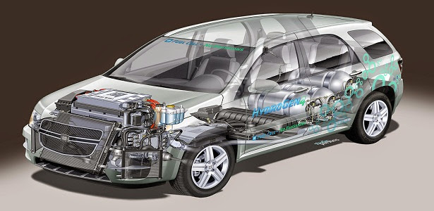
Hydrogen Fuel Cell !!! New source of 'R'energy

This is the world’s first scalable Hydrogen-On-Demand process requiring minimum power input

Download Free Android App For REnergy!!

This is a free android app for this blog : REnergy. I've built this app for the users of my blog to access my posts, works with ease.

Tuesday, 23 April 2013

Mahindra Reva launches all-electric car in Chandigarh

Mahindra Reva, country's electric vehicle pioneer, part of the USD 15.9 billion Mahindra Group, today unveiled its all-electric, zero-emission 'Mahindra e2o'in Chandigarh which would be available at a per month cost of Rs 12,802 (including EMI and running cost).
Speaking on the launch, Arun Malhotra, Chief Sales and Customer Care Officer, Automotive Division, Mahindra and Mahindra said "We are certain that the cutting-edge technological innovation that has gone into the Mahindra e2o will help customers remain connected in a convenient and cost-effective manner."


"Electric cars have always had the potential to emerge as a serious alternative to fossil fuel driven vehicles. Prospective customers have a choice in their hands as they now have the opportunity of shaping the future of mobility" said R Chandramouli, Chief of Operations, Mahindra Reva Electric Vehicles Private Limited.
The company has made a case to Chandigarh Administration for a subsidy of about 30 per cent on the total cost of the car which otherwise comes to about Rs 918 lakh in Chandigarh(Rs 12,802 per month installment for five years plus Rs 1.50 lakh down payment). which is in Chandigarh. the new car would be available in Chandigarh at a price of about Rs nine lakhHe said that Mahindra e2o is an Electric Vehicle (EV) designed as an urban mobility solution for a sustainable zero-emission society and gains relevance in the face of issues like environmental degradation, pollution related health concerns and climate change. Powered by lithium–ion batteries and a three phase induction electric motor; the new car is fully automatic and designed for city driving with no changing of gears in bumper-to-bumper traffic. It can accommodate four adults and a driving range of 100 kms per charge. The smart phone application can help lock the car by simply sending it a lock command and activate the car's air-conditioning remotely. One can plug in to charge like the cell phone, laptop or tablet. It comes with factory fitted GPS navigation system, radio, DVD, Blue tooth and I-pod connectivity.
He said that no petrol or diesel means freedom from often increasing oil prices, the Mahindra e2o needs to be serviced only once a year that too at one's door step. It will be available in six colours-arctic silver, coral blue, eco green, oceanic white, spanish red and sunfire yellow.

New Green Buildings Coming Up In ISRO Campus!!

Space technology is getting a green lining to it these ‘power-less’ summer days. The Indian Space Research Organisation (ISRO) is embracing green building concepts and solar power big-time with the southern states, where  the space agency has most of its frontline facilities, starved of power this summer.
 ISRO has instructed all its units, including those in Kerala, that new green building technologies and ‘sun power’ are to be tapped to the utmost in new buildings coming up on their campuses.
 The space agency, which has some big missions lined up for this year, is chanting the energy conservation mantra quite seriously when it comes to day-to-day use of electricity on its campuses, ISRO chairman K Radhakrishnan said.
“We’ve been practising energy conservation for decades. But we are are fully aware of the current situation,” Radhakrishnan said.
 
“Two of our units, the National Remote Sensing Centre (NRSC) at Hyderabad and the National Atmospheric Research Laboratory near Tirupathi, have already begun tapping solar power.
 “New civil constructions coming up on our campuses will be using green technologies, especially how natural light can be exploited,” he said.
 Some ISRO facilities, like the Liquid Propulsion Systems Centre (LPSC) at Mahendragiri in Tamil Nadu, have test facilities which are real power-guzzlers. At the Vikram Sarabhai Space Centre (VSSC) at Thumba in Thiruvananthapuram, such tests are relatively rarer.
But those tests which indeed demand large amounts of electricity -  hypersonic wind tunnel tests and the plasma wind tunnel tests, for instance - are now performed during off-peak hours, VSSC director S Ramakrishnan said.
“The power crisis has not affected our work here so far. But definitely we have to think about alternative sources of energy in the days ahead,” he said.
 Energy conservation is the buzz-word at another ISRO unit in the district - the LPSC at Valiyamala.
Switch off fans and lights when not needed and go soft particularly on air conditioners, the staff have been told, LPSC director M C Dathan said.
“I’ve already issued a circular in this regard,” he said.


Please view my project report on 5KW BIPV solar power system.


Follow me on Academia.edu


Thank you for reading.please give your feedback!!

lifi-presentation


RF Device : A very Basic Tutorial

What is RF driver?
RF (Radio Frequency) driver is basically a Computer program that provides radio frequency voltage to an external power device.
But first we have to know a term Radio Frequency Identification (RFID), because to have a basic idea on RF driver knowledge of RFID is important.


Radio-frequency identification (RFID) is the wireless non-contact use of radio-frequency electromagnetic fields to transfer data, for the purposes of automatically identifying and tracking tags attached to objects. Some tags require no battery and are powered and read at short ranges via magnetic fields (electromagnetic induction). Others use a local power source and emit radio waves (electromagnetic radiation at radio frequencies). The tag contains electronically stored information which may be read from up to several meters away. Unlike a bar code, the tag does not need to be within line of sight of the reader and may be embedded in the tracked object.
RFID tags are used in many industries. An RFID tag attached to an automobile during production can be used to track its progress through the assembly line. Pharmaceuticals can be tracked through warehouses. Livestock and pets may have tags injected, allowing positive identification of the animal.
Since RFID tags can be attached to clothing, possessions, or even implanted within people, the possibility of reading personally-linked information without consent has raised privacy concerns.

I hope reading the above paras now you are able to understand the RFID technology. Let's have a look on RF drivers. So you can see that RF drivers are nothing but a hardware set on which a particular computer program is implemented/embeded to do a certain work. here the certain work is to provide Radio Frequency voltage to an external power device. This external power device is almost in every cases are Power Amplifiers for HighTech user-end.

How RF Device Works?

Problems and concerns

Data flooding

Not every successful reading of a tag (observation) represents data useful for the purposes of the business. A large amount of data may be generated that is not useful for managing inventory or other applications. For example, a customer moving a product from one shelf to another, or a pallet load of articles that passes several readers while being moved in a warehouse, are events that do not produce data that is meaningful to an inventory control system.
Event filtering is required to reduce this data inflow to a meaningful depiction of moving goods passing a threshold. Various concepts have been designed, mainly offered as middleware performing the filtering from noisy and redundant raw data to significant processed data.

Global standardization

The frequencies used for RFID in the USA are currently incompatible with those of Europe or Japan. Furthermore, no emerging standard has yet become as universal as the barcode. To address international trade concerns, it is necessary to use a tag that is operational within all of the international frequency domains.

Security concerns

Retailers such as Walmart, which already heavily use RFID technology for inventory purposes, also use RFID as an anti-employee-theft and anti-shoplifting technology. If a product with an active RFID tag passes the exit-scanners at a Walmart outlet, not only does it set off an alarm, but it also tells security personnel exactly what product to look for in the shopper's cart.
A primary RFID security concern is the illicit tracking of RFID tags. Tags, which are world-readable, pose a risk to both personal location privacy and corporate/military security. Such concerns have been raised with respect to the United States Department of Defense's recent adoption of RFID tags for supply chain management. More generally, privacy organizations have expressed concerns in the context of ongoing efforts to embed electronic product code (EPC) RFID tags in consumer products. This is mostly as result of the fact that RFID tags can be read, and legitimate transactions with readers can be eavesdropped, from non-trivial distances. RFID technology used in access control, payment and eID (e-passport) systems operate at a shorter range than EPC RFID systems but are also vulnerable to skimming and eavesdropping, albeit at shorter distance.
A second method of prevention is by using cryptography. Rolling codes and challenge-response authentication (CRA) are commonly used to foil monitor-repetition of the messages between the tag and reader; as any messages that have been recorded would prove to be unsuccessful on repeat transmission. Rolling codes rely upon the tag's id being changed after each interrogation, while CRA uses software to ask for a cryptographically coded response from the tag. The protocols used during CRA can be symmetric, or may use public key cryptography.
Security concerns exist in regard to privacy over the unauthorized reading of RFID tags, as well as security concerns over server security. Unauthorized readers can use the RFID information to track the package, and so the consumer or carrier, as well as identify the contents of a package. Several prototype systems are being developed to combat unauthorized reading, including RFID signal interruption, as well as the possibility of legislation, and 700 scientific papers have been published on this matter since 2002. There are also concerns that the database structure of servers for the readers may be susceptible to infiltration, similar to denial-of-service attacks, after the EPCglobal Network ONS root servers were shown to be vulnerable.

Exploitation

Ars Technica reported in March 2006 an RFID buffer overflow bug that could infect airport terminal RFID databases for baggage, and also passport databases to obtain confidential information on the passport holder.

Passports

In an effort to make passports more secure, several countries have implemented RFID in passports. However, the encryption on UK chips was broken in under 48 hours. Since that incident, further efforts have allowed researchers to clone passport data while the passport is being mailed to its owner. Where a criminal used to need to secretly open and then reseal the envelope, now it can be done without detection, adding some degree of insecurity to the passport system.

Shielding

In an effort to prevent the passive “skimming” of RFID-enabled cards or passports, the U.S. General Services Administration (GSA) issued a set of test procedures for evaluating electromagnetically opaque sleeves. For shielding products to be in compliance with FIPS-201 guidelines, they must meet or exceed this published standard. Shielding products currently evaluated as FIPS-201 compliant are listed on the website of the U.S. CIO’s FIPS-201 Evaluation Program. The United States government requires that when new ID cards are issued, they must be delivered with an approved shielding sleeve or holder.

Shielding controversy

There are contradicting opinions as to whether aluminum can prevent reading of RFID chips. Some people claim that aluminum shielding, essentially creating a Faraday cage, does work. Others claim that simply wrapping an RFID card in aluminum foil only makes transmission more difficult and is not completely effective at preventing it.
Shielding effectiveness depends on the frequency being used. Low-frequency LowFID tags, like those used in implantable devices for humans and pets, are relatively resistant to shielding, though thick metal foil will prevent most reads. High frequency HighFID tags (13.56 MHz—smart cards and access badges) are sensitive to shielding and are difficult to read when within a few centimetres of a metal surface. UHF Ultra-HighFID tags (pallets and cartons) are difficult to read when placed within a few millimetres of a metal surface, although their read range is actually increased when they are spaced 2–4 cm from a metal surface due to positive reinforcement of the reflected wave and the incident wave at the tag. UHFID tags can be successfully shielded from most reads by being placed within an antistatic bag.

Temperature exposure

Currently, RFID tags are created by gluing an integrated circuit (IC) to an inlay. This poses a problem as vibration and high temperatures will loosen the connection. If the IC loses connection with the inlay, the RFID tag will no longer transmit. A new design was filed for patent (currently pending approval) where the IC is soldered to a circuit board and the circuit board is then soldered to the inlay. This process replaces the adhesive with solder which is much more durable and temperature resistant.


Thank you for reading. please give your valuable feedback & dont forget to follow the blog!!

Soaring on the power of the sun: World's most advanced solar plane flies


The world's most advanced solar-powered plane successfully carried out its latest test flight on Tuesday, soaring at 3,000 feet above the Bay Area of California and the iconic Golden Gate Bridge.


The Solar Impulse, which weighs only about 3,500 pounds, runs completely on power from the sun drawn from 12,000 solar cells that send energy into batteries that power propellers running on four electric motors.
Tuesday's flight was a technical test run to prepare for a planned cross-country trip beginning in early May.

Read more @ Dailymail

Sunday, 21 April 2013

Solar PhotoVoltaic : Basic Overview & Working Principle

Today i'm going to share some very very basic concepts/information on solar energy-specially on Solar Photo Voltaic. the reason behind this post is for some viewers of my blog asking me(actually mailing me) what is solar PV, how it works etc. So let's start discussing!!

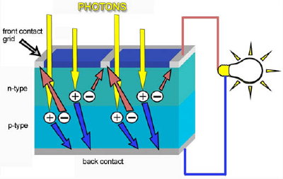
The sunlight reaching the Earth’s surface generates six thousand times more than the estimated 15 Terawatts (TW) of power consumed around the globe every year. It’s no wonder then, that mankind has long sought to capture and use the power of the sun. The challenge has always been the efficiency of capture and distribution.The current generated by the flow of electrons, when metal contacts are placed above and below the photovoltaic cell, can be extracted for external use. Solar cells, then, are the essential component in photovoltaic systems.


 To generate sufficient voltage, multiple cells are then interconnected to make up a solar panel.By leveraging capabilities of the photovoltaic process, as photons of sunlight, comprised of energy particles of different wavelengths hit a photovoltaic cell, their energy is transferred to the electrons which become part of a current in an electrical circuit.


How Silicon Makes a Solar Cell

Silicon has some special chemical properties, especially in its crystalline form. An atom of sili­con has 14 electrons, arranged in three different shells. The first two shells -- which hold two and eight electrons respectively -- are completely full. The outer shell, however, is only half full with just four electrons. A silicon atom will always look for ways to fill up its last shell, and to do this, it will share electrons with four nearby atoms. It's like each atom holds hands with its neighbors, except that in this case, each atom has four hands joined to four neighbors. That's what forms thecrystalline structure, and that structure turns out to be important to this type of PV cell.
The only problem is that pure crystalline silicon is a poor conductor of electricity because none of its electrons are free to move about, unlike the electrons in more optimum conductors like copper. To address this issue, the silicon in a solar cell has impurities -- other atoms purposefully mixed in with the silicon atoms -- which changes the way things work a bit. We usually think of impurities as something undesirable, but in this case, our cell wouldn't work without them. Consider silicon with an atom of phosphorous here and there, maybe one for every million silicon atoms. Phosphorous has five electrons in its outer shell, not four. It still bonds with its silicon neighbor atoms, but in a sense, the phosphorous has one electron that doesn't have anyone to hold hands with. It doesn't form part of a bond, but there is a positive proton in the phosphorous nucleus holding it in place.
When energy is added to pure silicon, in the form of heat for example, it can cause a few electrons to break free of their bonds and leave their atoms. A hole is left behind in each case. These electrons, called free carriers, then wander randomly around the crystalline lattice looking for another hole to fall into and carrying an electrical current. However, there are so few of them in pure silicon, that they aren't very useful.
But our impure silicon with phosphorous atoms mixed in is a different story. It takes a lot less energy to knock loose one of our "extra" phosphorous electrons because they aren't tied up in a bond with any neighboring atoms. As a result, most of these electrons do break free, and we have a lot more free carriers than we would have in pure silicon. The process of adding impurities on purpose is called doping, and when doped with phosphorous, the resulting silicon is called N-type ("n" for negative) because of the prevalence of free electrons. N-type doped silicon is a much better conductor than pure silicon.
The other part of a typical solar cell is doped with the element boron, which has only three electrons in its outer shell instead of four, to become P-type silicon. Instead of having free electrons, P-type ("p" for positive) has free openings and carries the opposite (positive) charge.

There are a few different technologies that support the photovoltaic process. The most commonly deployed solar panels in today’s market are comprised of solar cells that are made of silicon. Silicon (sand) is the second most abundant element in the Earth’s crust and the very same element that makes computer chips possible. The cell consists of two or more thin layers of semiconductor material. The layers are given opposite charges – one positive, one negative. When sunlight strikes the solar cell, electrons are knocked loose and move toward the treated front surface of the solar cell. This creates an electron imbalance between the front and back of the cell and causes electricity to flow – the greater the intensity of light, the greater the flow of electricity.
With steadily rising costs for carbon based fuels, concerns over their impact on the environment, and various incentives in place to help solar adoption, continued innovation in photovoltaics continues to helping to deliver on the power of the sun.


Thank you for reading!!

Follow me on Academia.edu
About the Author

Amrit Mandal is a final year B.tech (EE) Student, Admin of this blog. He likes to work in the renewable energy field-specially in solar energy field.
Follow Us on Twitter #REnergy_Blog

REnergy


Saturday, 20 April 2013

...সে দিনের অপেক্ষা !!


This blog is all about the poems, literatures and a kind of auto-bio of my friend Timir Baran Roy.the poems in this blog are all created by him. His facebook profile link is-Timir Baran Roy
He is a B.Tech Graduate from JU and doing M.Sc from Technical University of Lisbon,Portugal.
Timir also a contributor to this blog.

link to Timir's blog
thank you for reading!!

Dynamo based electronics device charger


Mobile electronics devices has become as fundamental need in our life as air, water, roof & cloths are. Cisco report says number of smart phones, tablets, laptops and internet-capable phones will exceed number of humans in 2013. 


To charge up this large number of devices, a large amount of electricity is required, which will be non-providable in recent years. In another way for environmental issue we have to save energy to save the earth. Engineers have found a smart & conventional way to solve the problem.
A dynamo can be attached to a mobile device charger through which the device can be powered without a power supply from main. This device requires three basic things: a dynamo, an AC to DC converter & a battery to store the power.


There are some interesting ways to generate power through dynamo & charge your mobile:

  • Attach the dynamo to your front wheel of a bicycle just like it was seen in 1970-1980.
  • Now when dynamo runs with the cycle synchronously, it'll produce AC power(3V, 6Watts or 12V 6 watts).
  • User can utilise the power in two ways--1)use a AC/DC converter unit and stores the power direct to a battery for later use of powe Or 2) using a simple AC/DC conversion unit utilise the DC output power(from conversion) to the mobile charger. 


  • Using Hand tool  
    • Multiple use – Mobile charger
    • No batteries needed. No plug power charging
    • 1 minute cranking generates energy for 15 minutes of lighting
    • 1 minute cranking provides 15/3 minutes of standby/talk time for mobile phones.
    • Lasts for 1000 cranking cycles. (1 cranking cycle = 1 minute cranking)
     

  • The dynamo may be attached to some other useful things like workout cycles in gym. It will save time and energy as well as recover your health issues. 

Economic prospects:
  • Easy to install
  • Reliable cost
  • Energy & time saving
  • Charge your phones anytime
  • Small reduction of home electricity bills
  •  Eco friendly


Nokia has come upwith a dynamo based bicycle charger in 2010. Charging times will obviously vary depending on the phone and cycling speeds, but Nokia says cycling for 20 minutes at 20 kmh (12.4 mph) will power up a Nokia 1202 for around one hour of talk time, or 74 hours of standby time. Charging starts when the cyclist hits walking speed, or around 6 km/h (3.7 mph), and at 12 km/h (7.4 mph) it will charge your phone as efficiently as a mains charger. And there’s no need to worry about going to fast and sending a power spike to your phone as the charger will cut out if you somehow exceed 50 km/h (31 mph). The kit consists of three components: a bottle dynamo, charger and a phone holder. Nokia’s Bicycle Charger Kit is compatible with any Nokia phone with a 2 mm charging interface and is easy to install.


Advanced Earthquake Resistant Design Techniques

Intro

The conventional approach to earthquake resistant design of buildings depends upon providing the building with strength, stiffness and inelastic deformation capacity which are great enough to withstand a given level of earthquake–generated force. This is generally accomplished through the selection of an appropriate structural configuration and the careful detailing of structural members, such as beams and columns, and the connections between them.

(fig. 1)


In contrast, we can say that the basic approach underlying more advanced techniques for earthquake resistance is not to strengthen the building, but to reduce the earthquake–generated forces acting upon it. Among the most important advanced techniques of earthquake resistant design and construction are base isolation and energy dissipation devices.

Base Isolation

It is easiest to see this principle at work by referring directly to the most widely used of these advanced techniques, which is known as base isolation. A base isolated structure is supported by a series of bearing pads which are placed between the building and the building's foundation.(See Figure 1) A variety of different types of base isolation bearing pads have now been developed. For our example, we'll discuss lead–rubber bearings. These are among the frequently–used types of base isolation bearings. (See Figure 2) A lead–rubber bearing is made from layers of rubber sandwiched together with layers of steel. In the middle of the bearing is a solid lead "plug." On top and bottom, the bearing is fitted with steel plates which are used to attach the bearing to the building and foundation. The bearing is very stiff and strong in the vertical direction, but flexible in the horizontal direction.

Earthquake Generated Forces


(fig. 2)
To get a basic idea of how base isolation works, first examine Figure 3. This shows an earthquake acting on both a base isolated building and a conventional, fixed–base, building. As a result of an earthquake, the ground beneath each building begins to move. In Figure 3, it is shown moving to the left.
Each building responds with movement which tends toward the right. We say that the building undergoes displacement towards the right. The building's displacement in the direction opposite the ground motion is actually due to inertia. The inertial forces acting on a building are the most important of all those generated during an earthquake.
It is important to know that the inertial forces which the building undergoes are proportional to the building's acceleration during ground motion. It is also important to realize that buildings don't actually shift in only one direction.
Because of the complex nature of earthquake ground motion, the building actually tends to vibrate back and forth in varying directions. So, Figure 3 is really a kind of "snapshot" of the building at only one particular point of its earthquake response.

(fig. 3)
In addition to displacing toward the right, the un–isolated building is also shown to be changing its shape– from a rectangle to a parallelogram. We say that the building is deforming. The primary cause of earthquake damage to buildings is the deformation which the building undergoes as a result of the inertial forces acting upon it.
The different types of damage which buildings can suffer are quite varied and depend upon a large number of complicated factors. But to take one simple example, one can easily imagine what happens to two pieces of wood joined at a right angle by a few nails, when the very heavy building containing them suddenly starts to move very quickly — the nails pull out and the connection fails.

Response of Base Isolated Building

By contrast, even though it too is displacing, the base–isolated building retains its original, rectangular shape. It is the lead–rubber bearings supporting the building that are deformed. The base–isolated building itself escapes the deformation and damage—which implies that the inertial forces acting on the base–isolated building have been reduced.
Experiments and observations of base–isolated buildings in earthquakes have been shown to reduce building accelerations to as little as 1/4 of the acceleration of comparable fixed–base buildings, which each building undergoes as a percentage of gravity. As we noted above, inertial forces increase, and decrease, proportionally as acceleration increases or decreases.
Acceleration is decreased because the base isolation system lengthens a building's period of vibration, the time it takes for the building to rock back and forth and then back again. And in general, structures with longer periods of vibration tend to reduce acceleration, while those with shorter periods tend to increase or amplify acceleration.
Finally, since they are highly elastic, the rubber isolation bearings don't suffer any damage. But what about that lead plug in the middle of our example bearing? It experiences the same deformation as the rubber. However, it also generates heat as it does so.
In other words, the lead plug reduces, or dissipates, the energy of motion—i.e., kinetic energy—by converting that energy into heat. And by reducing the energy entering the building, it helps to slow and eventually stop the building's vibrations sooner than would otherwise be the case —in other words, it damps the building's vibrations. (Damping is the fundamental property of all vibrating bodies which tends to absorb the body's energy of motion, and thus reduce the amplitude of vibrations until the body's motion eventually ceases.)

Spherical Sliding Isolation Systems

As we said earlier, lead–rubber bearings are just one of a number of different types of base isolation bearings which have now been developed. Spherical Sliding Isolation Systems are another type of base isolation. The building is supported by bearing pads that have a curved surface and low friction.

(fig. 4)
During an earthquake, the building is free to slide on the bearings. Since the bearings have a curved surface, the building slides both horizontally and vertically (See Figure 4.) The force needed to move the building upwards limits the horizontal or lateral forces which would otherwise cause building deformations. Also, by adjusting the radius of the bearing's curved surface, this property can be used to design bearings that also lengthen the building's period of vibration.
For more information read this article titled Protective Systems for Buildings: Application of Spherical Sliding Isolation Systems as it describes one particular type of spherical sliding isolation system, and its successful use in making some structures more earthquake resistant.

Energy Dissipation Devices

The second of the major new techniques for improving the earthquake resistance of buildings also relies upon damping and energy dissipation, but it greatly extends the damping and energy dissipation provided by lead–rubber bearings.
As we've said, a certain amount of vibration energy is transferred to the building by earthquake ground motion. Buildings themselves do possess an inherent ability to dissipate, or damp, this energy. However, the capacity of buildings to dissipate energy before they begin to suffer deformation and damage is quite limited.
The building will dissipate energy either by undergoing large scale movement or sustaining increased internal strains in elements such as the building's columns and beams. Both of these eventually result in varying degrees of damage. So, by equipping a building with additional devices which have high damping capacity, we can greatly decrease the seismic energy entering the building, and thus decrease building damage.
Accordingly, a wide range of energy dissipation devices have been developed and are now being installed in real buildings. Energy dissipation devices are also often called damping devices. The large number of damping devices that have been developed can be grouped into three broad categories:
  • Friction Dampers– these utilize frictional forces to dissipate energy
  • Metallic Dampers– utilize the deformation of metal elements within the damper
  • Viscoelastic Dampers– utilize the controlled shearing of solids
  • Viscous Dampers– utilized the forced movement (orificing) of fluids within the damper

Fluid Viscous Dampers

Once again, to try to illustrate some of the general principles of damping devices, we'll look more closely at one particular type of damping device, the Fluid Viscous Damper, which is one variety of viscous damper that has been widely utilized and has proven to be very effective in a wide range of applications.
The article, titled Application of Fluid Viscous Dampers to Earthquake Resistant Design, describes the basic characteristics of fluid viscous dampers, the process of developing and testing them, and the installation of fluid viscous dampers in an actual building to make it more earthquake resistant.

Damping Devices and Bracing Systems


(fig. 5)
Damping devices are usually installed as part of bracing systems. Figure 5 shows one type of damper–brace arrangement, with one end attached to a column and one end attached to a floor beam. Primarily, this arrangement provides the column with additional support.
Most earthquake ground motion is in a horizontal direction; so, it is a building's columns which normally undergo the most displacement relative to the motion of the ground. Figure 5 also shows the damping device installed as part of the bracing system and gives some idea of its action.

Source:

 Research work mainly in US
 

Friday, 19 April 2013

"Unlike poles attract & like poles repel”- a machine works on this statement


   Unlike poles attract & like poles repel”- a machine works on this statement is REPULSION MOTOR.
in this post i'll discussion some basics of repulsion motor.


A repulsion motor is a type of electric motor f or use on alternating current (AC). It was f ormerly usedas a traction motor f or electric trains but has been superseded by other types of motors and is now onlyof historical interest. Repulsion motors are classif ied under single phase motors. In repulsion motors thestator windings are connected directly to the AC power supply and the rotor is connected to acommutator and brush assembly, similar to that of a direct current (DC) motor


Construction

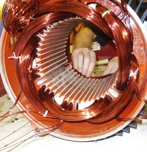
The motor has a stator and a rotor but there is no electrical connection between the two and the rotor
current is generated by induction. The rotor winding is connected to a commutator which is in contact
with a pair of short-circuited brushes which can be moved to change their angular position relative to an
imaginary line drawn through the axis of the stator. The motor can be started, stopped and reversed, and
the speed can be varied, simply by changing the angular position of the brushes.


Voltage

Most commutator motors are limited to about 1,500 volts because higher voltages give rise to a risk of
arcing across the commutator. Repulsion motors can be used at higher voltages because the rotor circuit
is not electrically connected to the supply.


Principle

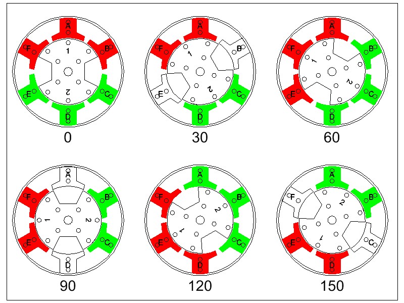
Repulsion motors are based on the principle of repulsion between two magnetic f ields. Consider a 2-pole
salient pole motor with a vertical magnetic axis. The armature is connected to a commutator and brushes.
The brushes are short circuited using a low-resistance jumper. When alternating current is supplied to
the f ield (stator) winding, it induces an electromotive f orce (emf ) in the armature. The direction of
alternating current is such that it creates a north pole at the top and a south pole at the bottom. The
direction of induced emf is given by Lenz's law, according to which the direction of induced emf opposes
the cause producing it. The induced emf induces current in the armature conductors and the direction of
the induced current depends on the position of the brushes.


Follow me on Academia.edu